Simulation setup
FABulous provides a simulation environment to validate that the generated FPGA fabric works correctly. The simulation loads a test bitstream, built from the user design, into the simulated FABulous fabric RTL and verifies that configuration, routing, and primitive behavior function as intended.
        flowchart TB
    subgraph design ["User Design Flow"]
        A[User Design Verilog/VHDL] --> B[Yosys Synthesis]
        B --> C[nextpnr Place & Route]
        C --> D[Bitstream Generation]
    end

    subgraph fabric ["Fabric Generation"]
        F[FABulous] --> G[Fabric RTL]
    end

    subgraph sim ["Simulation"]
        direction LR
        E[Test Bitstream] --> H["Testbench (iverilog / GHDL)"]
        H --> I{Pass / Fail}
    end

    subgraph emu ["Emulation"]
        direction LR
        J[Hardwired Bitstream] --> K[Fabric RTL + Bitstream]
        K --> L[Commercial FPGA Board]
    end

    D --> E
    D --> J
    G --> H
    G --> K
Important
The purpose of FABulous simulation is to verify the generated fabric implementation, not to validate user designs mapped onto it. If you need to test your own design logic, use a standard HDL testbench for your design before mapping it to the fabric.
The following diagram illustrates the simulation flow and how the different components interact.
        flowchart LR
    A[User Design Verilog/VHDL] --> B[Yosys Synthesis]
    B --> C[nextpnr Place & Route]
    C --> D[Bitstream Generation]
    D --> E[Test Bitstream]

    F[FABulous] --> G[Fabric RTL]

    E --> H[Testbench Simulation]
    G --> H
    H --> I{Pass / Fail}
For simple use cases, there is the run_simulation command in the FABulous shell.
For more complex use cases it can be useful to create your own flow using the
Taskfile.yml provided in each project’s Test/ directory.
Prerequisites
Please make sure to use recent versions of Yosys, nextpnr-generic (not the old FABulous nextpnr fork) and GHDL with mcode backend or use the OSS-CAD-Suite which provides nightly builds of the necessary dependencies.
Note
The OSS-CAD-Suite is providing GHDL only with LLVM backend, which increases the simulation speed for FABulous projects significantly. We recommend using the latest GHDL with mcode backend for the best simulation performance.
Taskfile
FABulous uses Taskfile (a modern, YAML-based task runner)
to manage the simulation build flow. Each project is created with a Taskfile.yml
in the Test/ directory that defines all the steps needed to synthesize, place
and route, generate bitstreams, and run simulations.
The task command is installed automatically as part of the FABulous package.
Running a simulation
From the project’s Test/ directory, run the full pipeline (build + simulate + clean)
with a single command.
cd demo/Test
task
To run individual steps, use the task name directly.
task build-test-design    # synthesize, place & route, generate bitstream
task run-simulation       # run the simulation only
task clean                # remove the build directory
To see all available tasks, run task --list.
Customizing variables
All key parameters are defined as variables at the top of Taskfile.yml and can
be overridden via the command line without editing the file.
task run-simulation DESIGN=my_design WAVEFORM_TYPE=vcd
The available variables are:
Variable |
Default |
Description |
|---|---|---|
|
|
Name of the user design (without extension) |
|
|
Top-level wrapper module name |
|
|
Waveform output format ( |
|
|
Build output directory |
|
|
Path to the project root |
|
|
GHDL compilation flags (VHDL only) |
|
|
Path to the |
|
(empty) |
Extra flags passed to iverilog (Verilog only) |
|
(empty) |
Extra flags passed to GHDL (VHDL only) |
|
|
Maximum bitstream size in bytes |
Variables can also be set via environment variables or the project’s
.FABulous/.env file (loaded automatically via dotenv).
Using the CLI
The run_simulation CLI command is a thin wrapper that invokes the Taskfile.
It takes the path to a .bin bitstream file generated by run_FABulous_bitstream,
converts it to the .hex format expected by the testbench, and then runs the
simulation via the Taskfile. The design name is inferred from the bitstream
filename unless overridden with -d.
# Basic usage (converts design.bin to hex and simulates)
FABulous> run_simulation fst path/to/design.bin

# Specify a different design name
FABulous> run_simulation fst path/to/design.bin -d my_design

# Pass extra simulator flags
FABulous> run_simulation fst path/to/design.bin --extra-iverilog-flag="-DDEBUG"
FABulous> run_simulation fst path/to/design.bin --extra-ghdl-flag="--warn-error"

# Combine options
FABulous> run_simulation vcd path/to/design.bin -d my_design -if "-DDEBUG -DTRACE"
Flag |
Short |
Description |
|---|---|---|
|
|
Override the design name (default: inferred from bitstream filename) |
|
|
Extra flags for iverilog (Verilog projects) |
|
|
Extra flags for GHDL (VHDL projects) |
Verilog vs. VHDL
Each project language gets its own Taskfile.yml tailored to the appropriate
toolchain.
Verilog projects use Icarus Verilog (
iverilog/vvp) for simulation.VHDL projects use GHDL for simulation. GHDL requires files to be compiled in dependency order, so the VHDL Taskfile compiles packages (
models_pack) first, then tile files, then fabric infrastructure, and finally the user design and testbench.
Note
The Taskfile.yml is a regular YAML file that you can freely edit to add
custom steps or adjust the flow for your project. See the
Taskfile documentation for the full reference.
Deprecated since version next: release
The legacy Makefile in Test/ is deprecated and will be removed in the
next release. Please migrate to Taskfile.yml. The FABulous CLI
(run_simulation) will prefer Taskfile.yml when present and fall back to
make with a deprecation warning.
FABulous comes with 3 different simulation methods:
Serial (Mode 0)
Send configuration in through UART
Parallel (Mode 1) - default in the testbench
Use parallel configuration port
Bitbang configuration port (To be supported in the testbench)
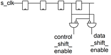
We have produced a quick asynchronous serial configuration port interface that is ideal for microcontroller configuration. It uses the original CPU interface that we have in our TSMC chip. The idea of the protocol is as follows:
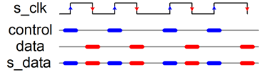
We drive s_clk and s_data. On each rising edge of s_clock, we sample data and on the falling edge, we sample control.
Both values get shifted in a separate register. If the control register sees the bit-pattern x”FAB0” it samples the data shift register into a hold register and issues a one-cycle strobe output (active 1).
The next figure shows the enable generation (and input sampling) for generating the enable signals for
the control shift register and
the data shift register.